The Bad Apple Case Mod - 2004
The Bad Apple pages have been reassembled for today's bandwidth, providing
larger illustrations. This article has become one of the most popular
features on barovelli.com. Enjoy.
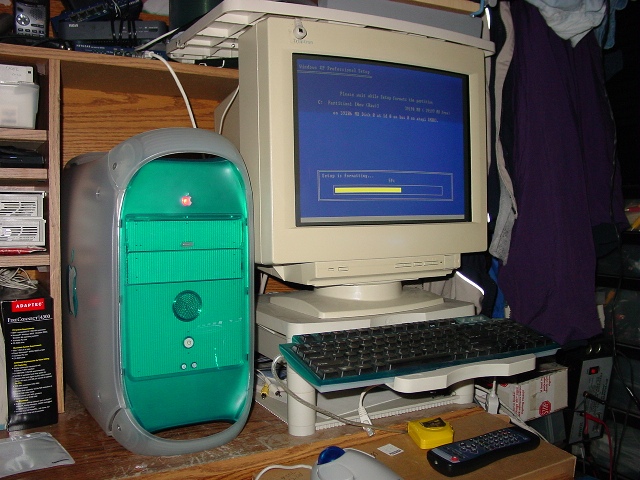
The next computer mod project, build a PC in a very recognizable Apple G3
case. This project does not attempt to build the wildest over clocked game
rig, or cram a pile of used parts into the case - this project is to make a
very 'sano' sleeper PC.
OBJECTIVES:
No obvious signs of a Windows PC - floppy disks, exposed beige CD ROMs,
missing I/O shields or run of the mill OEM beige keyboard.
No hot rod mods like blowholes, case windows, front USB or fire wire ports.
Incorporate every aspect of G3 operation to the PC contents. Panel buttons,
CD ROM and other parts work so easy that an Apple user could use it with no
instructions.
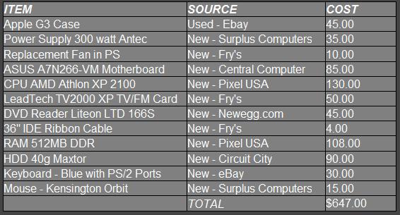
Cost of Project:
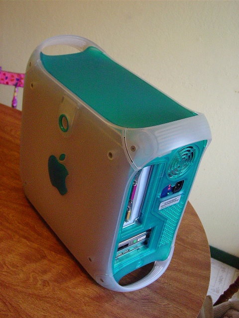
FITTING THE CASE
Straight from eBay - Apple G3 Blue& White tower case. Included all case covers, power switch, speaker, front drive cage, bottom drive platform, case fan & extra Zip drive bay cover. Cost: $44 plus $15 for shipping.
First - it needs some slightly more advanced modifications than just
stuffing a PC motherboard in the case and holding it all together with
Velcro & duct tape.
Cable Ties hold the board on
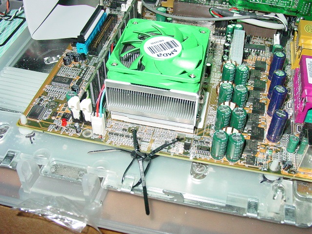
Ha ha - some sloppy, stuffing the board into the case pictures.
Wires hanging out.
Strip of tape to grip to open CD bay.
OK, SERIOUSLY FITTING THE CASE
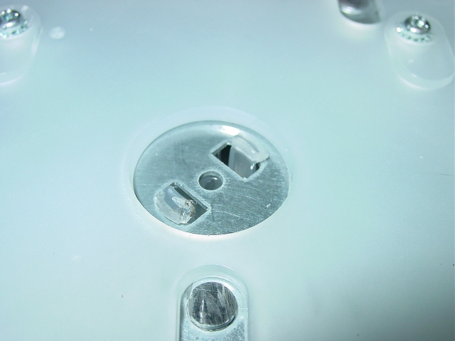
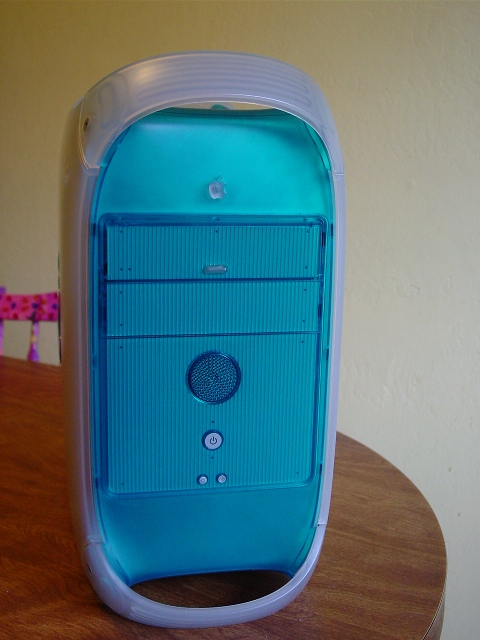
Strip the plastic off and set it aside. No modification is needed, and you
don't want to damage it. Remove the hex screws on the handles and covers.
The side panels snap into the center hole too.
You need to pinch the plastic 'hub' inside and push it out.
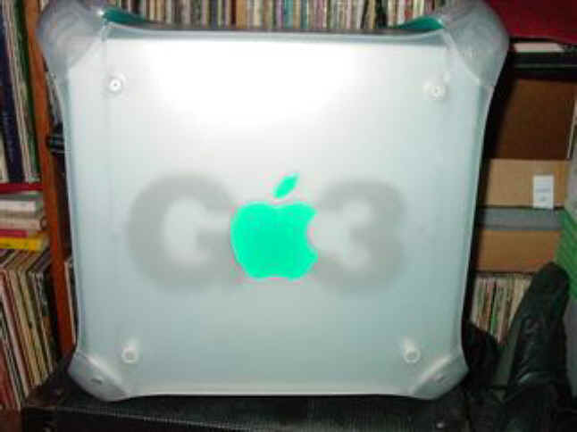
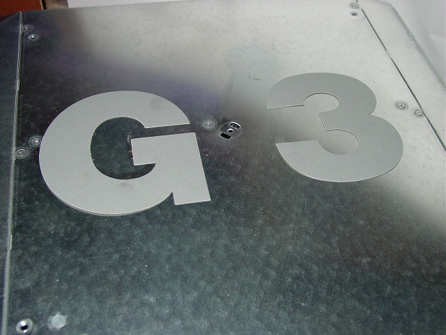
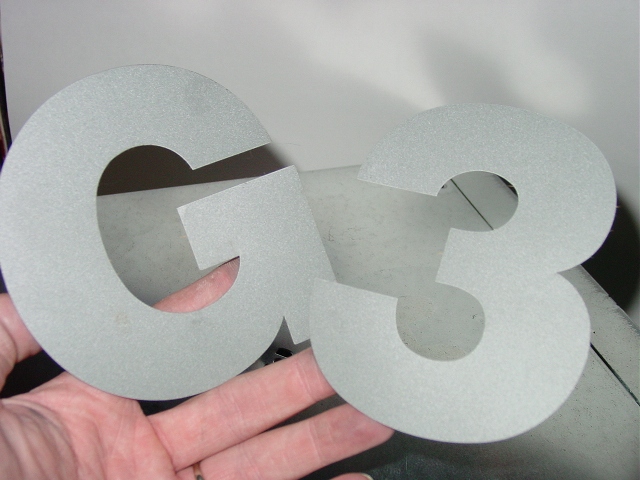
Cannot think of anything 'G 3' has to do with a PC, so peel off these
letters.
A Dremel or other cutting tool of choice cuts off all the Apple standoffs.
Don't ruin the 4 threaded bushings that hold the plastic matting that covers
the inside of the door. It is needed for latching the cover.
I test-fitted a motherboard, using some plastic standoffs. I put expansion
cards in the slots to line it up right.
Then using a sharpie pen through other empty mounting holes, I marked 3
mounting points.
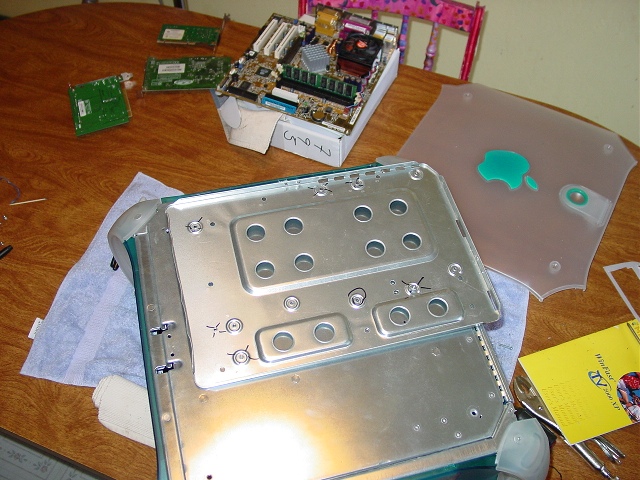
Taking an old motherboard mounting tray as a template, I used nuts & bolts
to attach it to the outside of the G3 case.
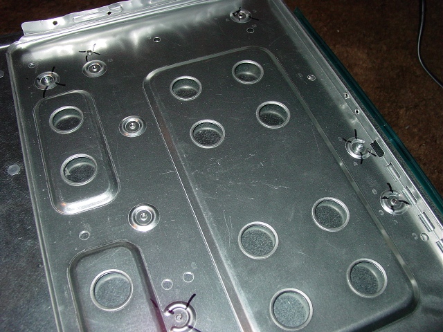
Drill a few more mounting holes, using the tray as a guide.

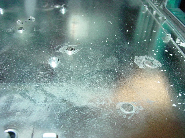
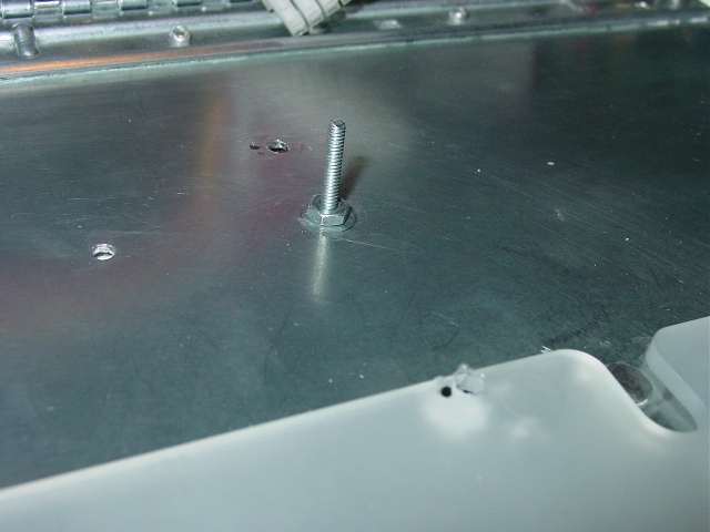
Take off the tray, and replace the bolts, this time with the ends inside the
case. I ran two nuts down the bolts this is what the motherboard will rest
on.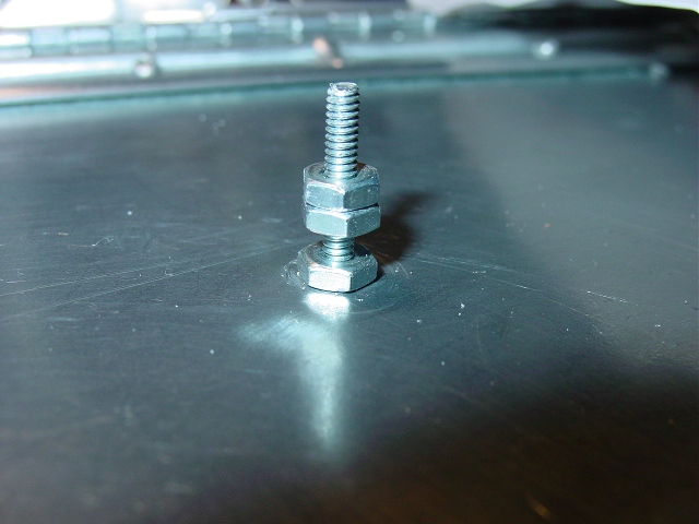
The motherboard will be secured with another nut.

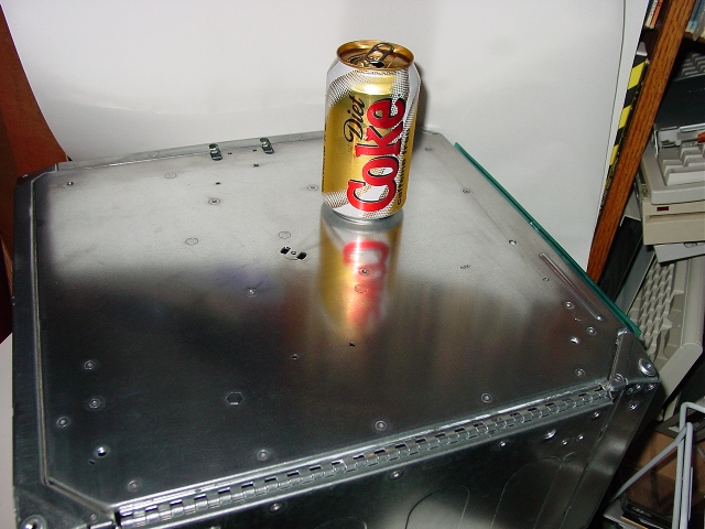
Clean up the case after all that grinding and drilling. A bit of chrome
polish took to it nice.
CASE FAN
The case fan is a 120mm fan. I swapped the stock fan with a speed-adjustable
one.
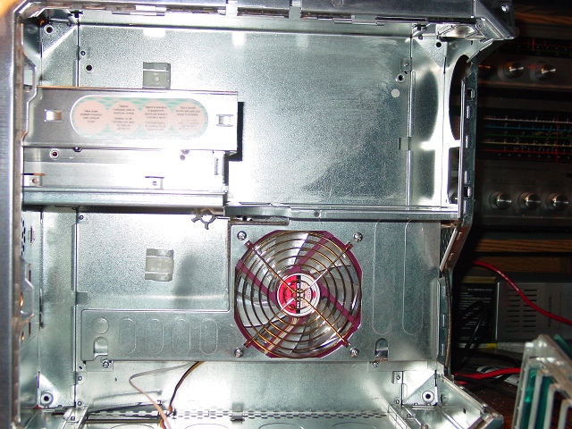
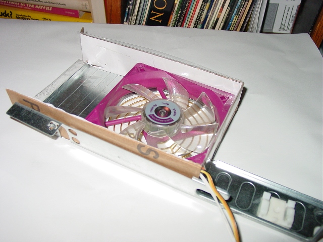
Instead of just blowing ambient air over the expansion cards, I built up a
shroud to make the fan pull air from the back vents. Just cardboard.
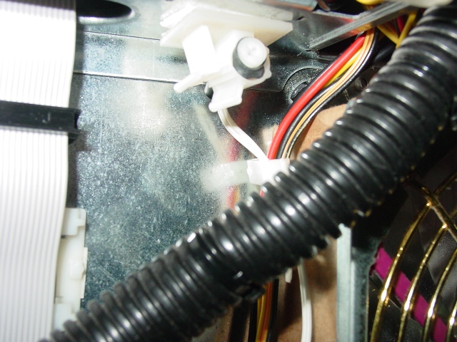
The fan speed adjustment control fits into a cable clip.
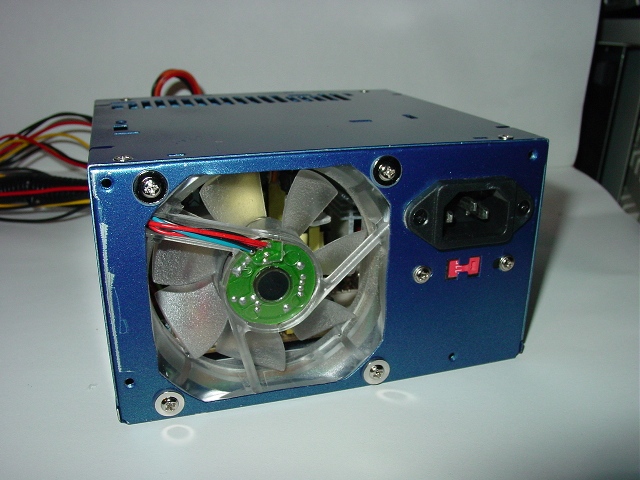
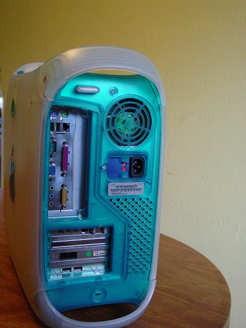
POWER SUPPLY
Power supply is an Antec 350 watt OEM pulled from another case. It fits the
G3's
cutout and mounting holes like it was made for it. A little detour to change
the fan.
Perfect Fit
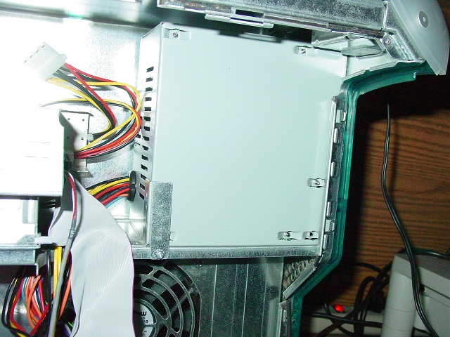
Stock Fan to remove.
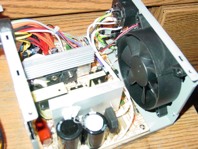
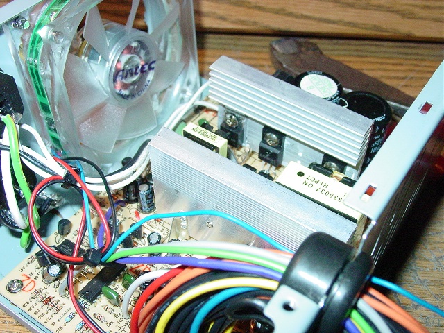
As long as we are this far - why not tear down the whole thing and paint it?
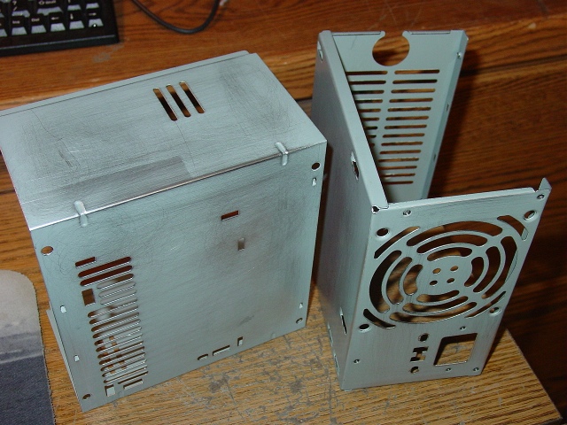
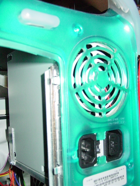
Since the G3 case has a fan grille, I cut the grille off of the power supply
case. Less surface for air to rush past.
Antec blue LED fan replaces the stock fan. A little blue paint from the
Mint.
Some blue paint from the Mint project.
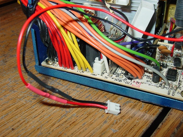
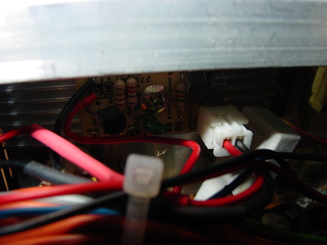
Neatness nut says to cut off the 4 conductor adaptor and solder a 2 pin plug
to the fan. This was then plugged into a Zalman fan speed controller.
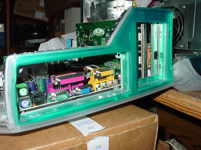
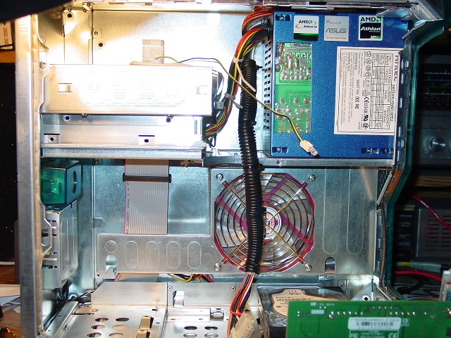
The window cutout exposes the circuitry. There is a clear plastic sheet in
the case insulating the circuit board. Not really the intention of the mod,
the CPU fan is smack up near the power supply in the case layout.
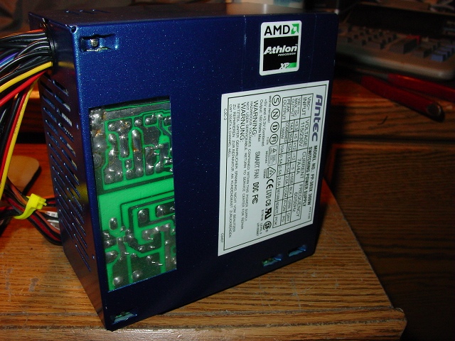
Breaking up the surface for anti-noise, and give the CPU fan a little
breathing room.
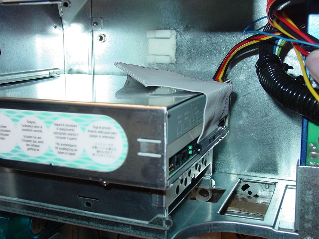
CD / DVD DRIVE
DVD ROM fits into a drive cage that slides into the case.
Sound simple? Oh no, not in this mod.
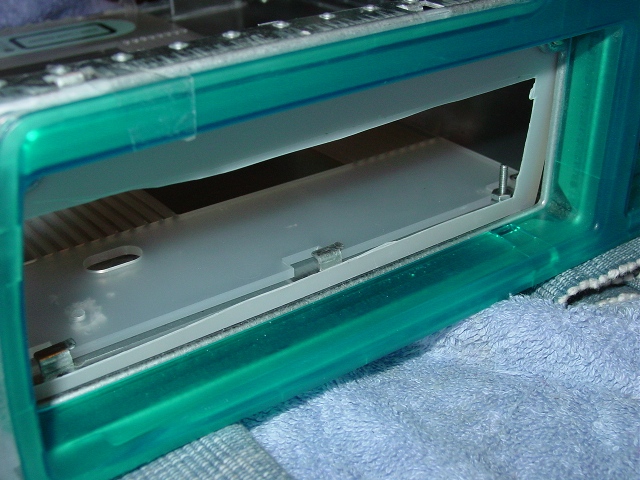
View behind the pretty face
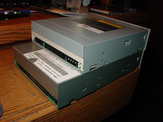
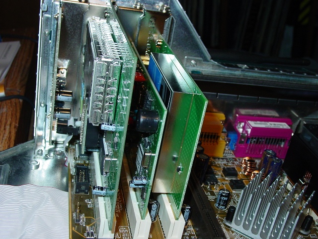
Check out the size of a standard old drive in the G3 cage. This is what
causes one to clip off memory sockets, reroute capacitors and carve CDROM
drives. Something this big will crunch against most any motherboard.
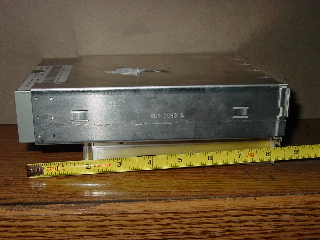
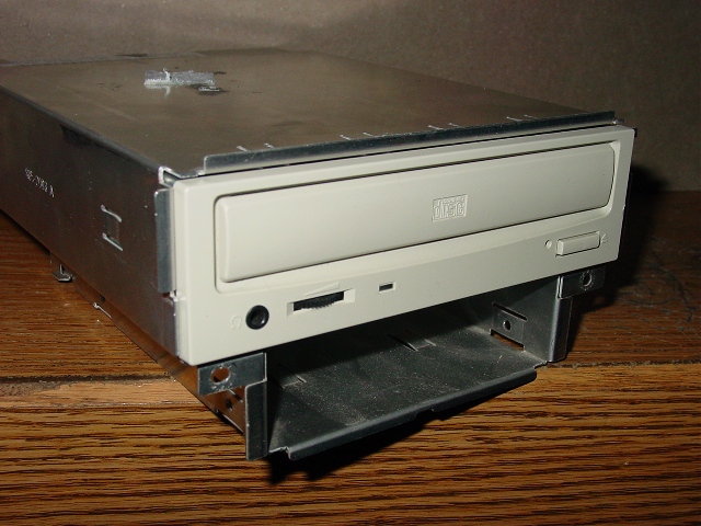
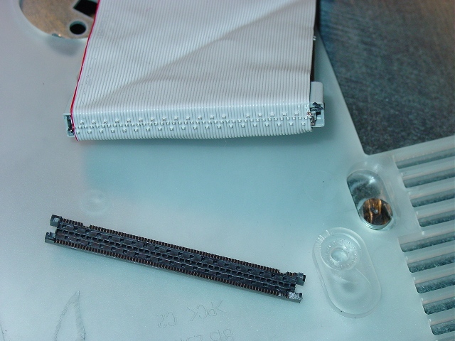
Enter the choice find: A LiteOn DVD ROM that is much shorter.
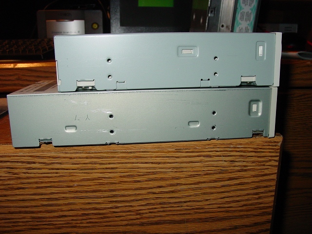
Quite a bit shorter
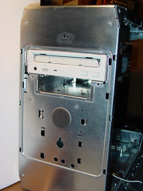
I installed the DVD into the G3 drive pocket, marked off and trimmed the
excess. Just aluminum, I used a nibbler tool for this. Look, no screws in
the side. There's a second set of case screws are under the drive.
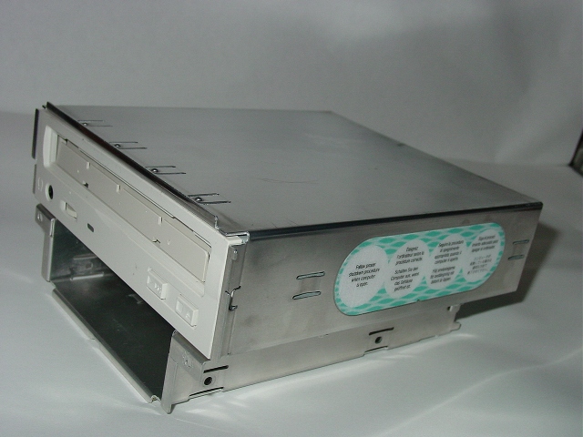
DVD ROM and drive bay Installed back in the case
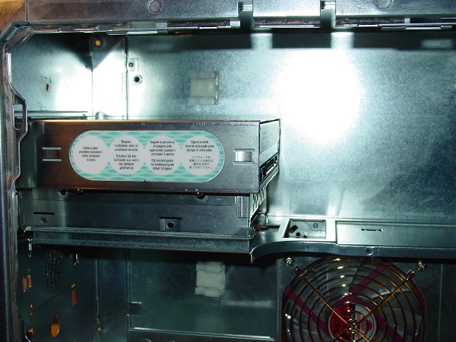
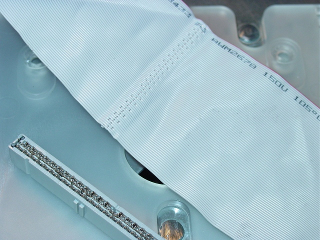
The IDE for the DVD comes off the board, turns and goes up the back of the
case. This needed a 36" ribbon cable.
Up, over and in. This stretched the limit of an IDE cable. 36".
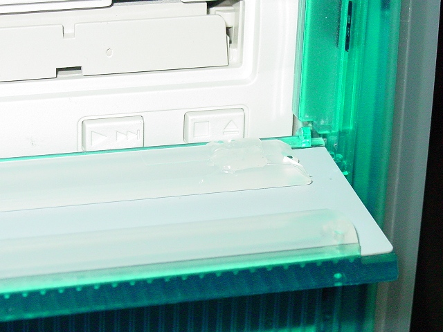
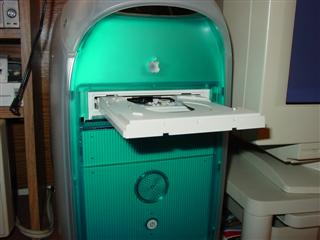
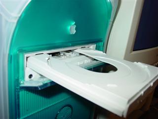
FRONT PANEL
To open the built in 'stealth' drive cover, there is a button in the middle
of the cover. It is supposed to push a plastic paddle that in turn depresses
the button on the stock drive. For my use, I had to build up the eject
button or the paddle. I chose to use some hot melt glue to make the paddle
contact the eject button.
Pull my finger. No no, push the button.
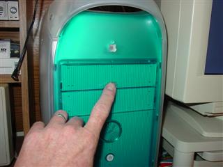
It works!!
I removed the front cover from the drive tray. It snaps on and off.
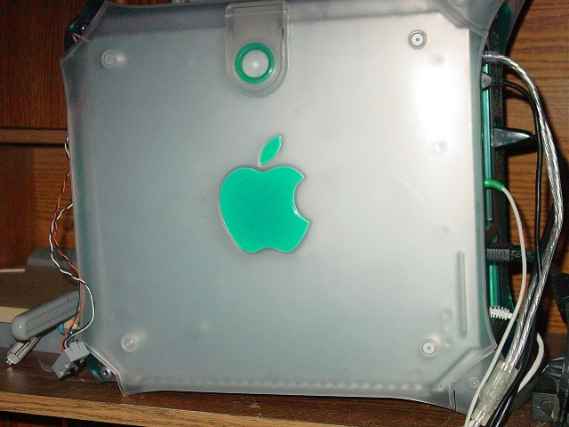
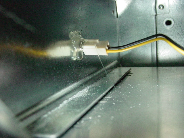
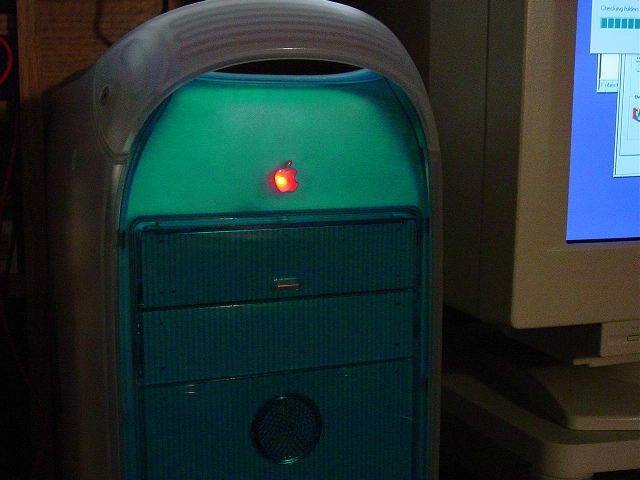
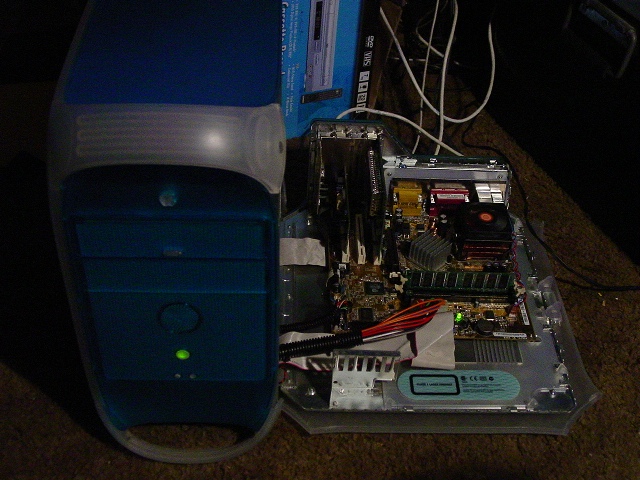
The little Apple logo on the front cover begs to be lit. A hole in the back
of the logo, with the HDD LED anchored with more hot glue lights up the
fruit.
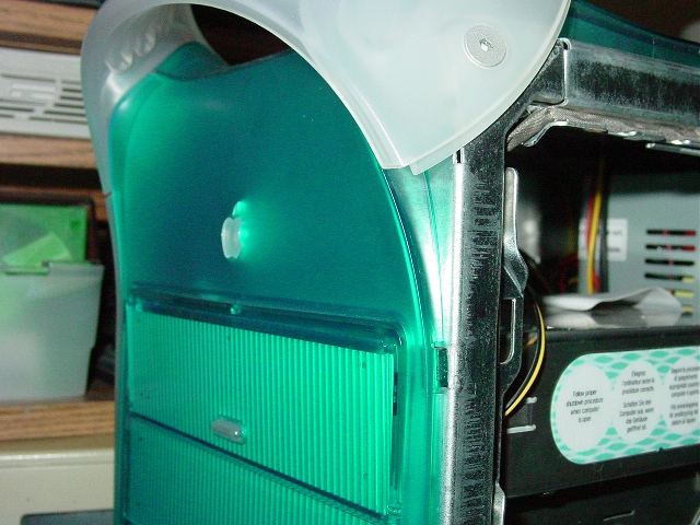
If a little glue is good . . .
This needs help, I know - good effect but really should be diffused so the
the entire logo lights with a uniform brightness.
The front panel buttons are plastic extensions to the actual switches in a
box on inside the case. The original switches can be rewired [ see ichau.com
]to work the Power-LED-Reset. I never did figure how to duplicate the
throbbing LED effect.
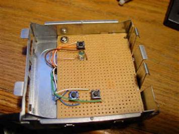
I instead chose to fabricate my own with micro switches, perfboard, an LED
and some CAT5 cable. ummm I love the smell of solder rosin burning in the
evening!
The power button was not the same depth as the reset/programmer buttons, I
filed down the extension on the inside of the case so the power switch was
not in a constant ON state.
Old motherboard front panel connectors spliced onto the CAT5 hook up to the
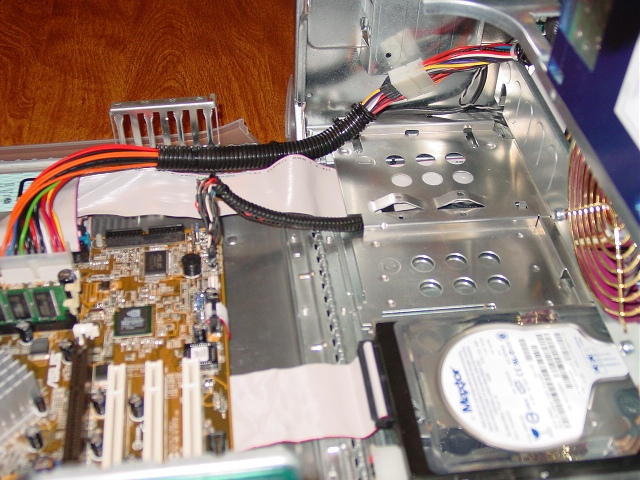
motherboard. Some split sleeve wrap bundles them all up.
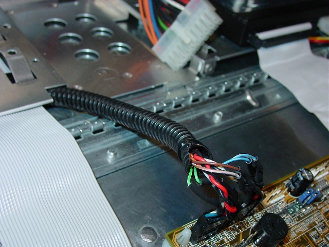
Routed behind the fan panel and under the hard drive tray.
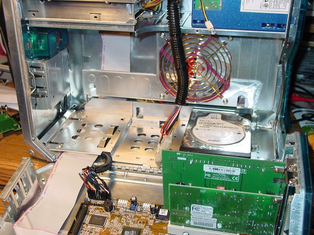
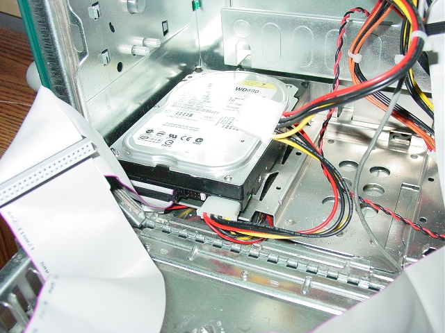
HARD DISK DRIVE
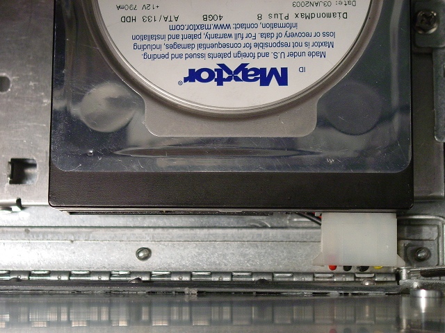
Hard drive sits on a tray that will hold 3 drives. For neatness, I put the
drive in the backmost bay.
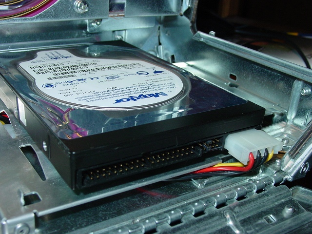
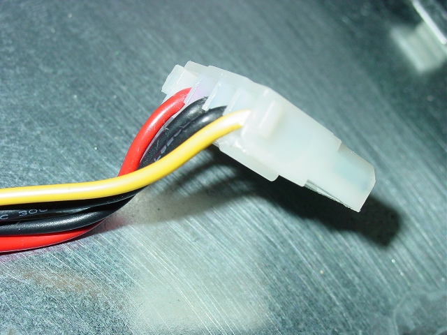
That power plug is too close to the limits of avoiding getting crushed by
the door closing. I cut down one side of the power plug.
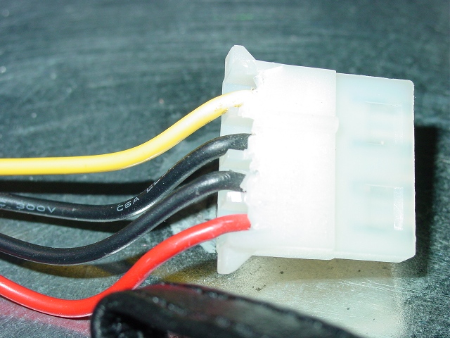
Instant right angle Molex.
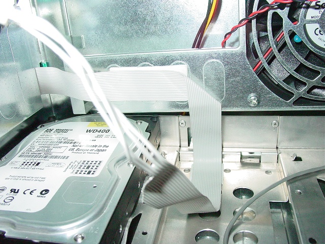
Test fit, close the door while peeking in.
The IDE cable will route under the motherboard, turn toward the case front .
. .
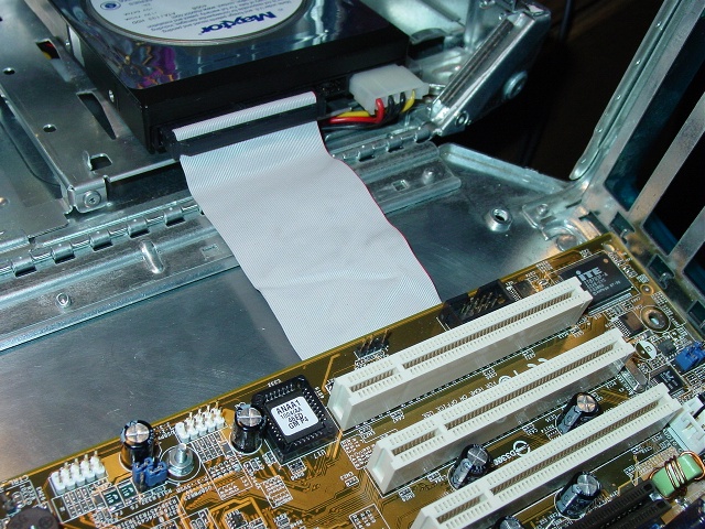
. . . and come up by the motherboard IDE socket.
The fit under the board was too tight, the slave plug and the plastic mat
would high center the motherboard at a critical point - the expansion cards.
So the slave plug pops right off starting with the top clip.
Peel off the bottom plug. Sort of like carpet stripping. Peel slowly.
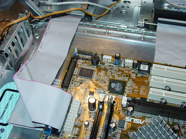
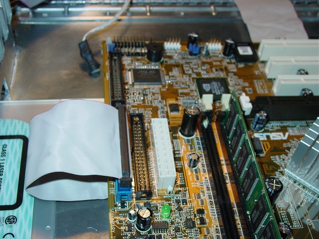
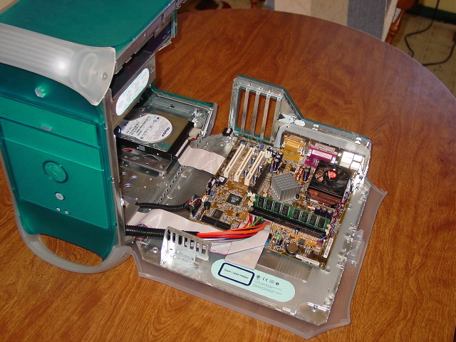
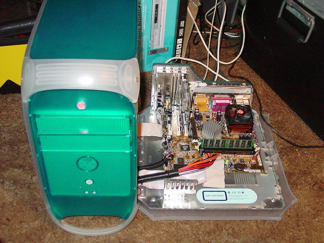
MOTHERBOARD
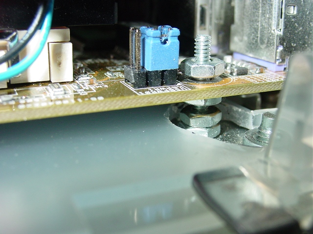
Set the motherboard on the mounting screws. A couple of the screws would
interfere with the sliding plastic mat, on one I elongated the hole, and at
another point I used the plastic standoffs to keep the board level.
I needed an extension cable for the ATX power plug, unless I wanted to
always unplug the power whenever the case was opened.
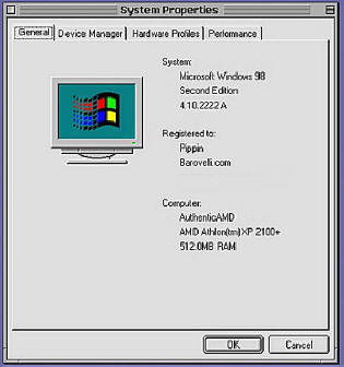
Board is an ASUS A7N266-VM. Fans of this site and others noticing
inconsistent photos may remember that I started with an ECS K7SEM.
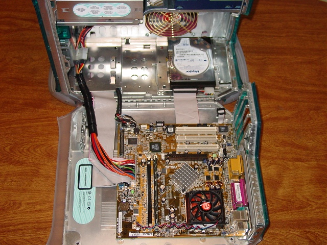
Fill the expansion slots. Left to right: ASUS USB (it's ribbon cable sneaks
under the board over to it's header. Leadtek XP2000 TV card, Creative Modem
Blaster, Linksys WIFI card.
That completes it.
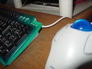
HUMAN INTERFACE
The Keyboard is one touch that really made this project look genuine. Same
blue color (even looks green in a camera flash), same basic shape of an
Apple keyboard.
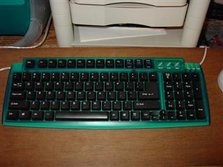
Carry the masquerade further by having a Y adaptor cable that combines the
mouse & keyboard plugs behind the PC into one lead. That lead is plugged
into one side of the keyboard.
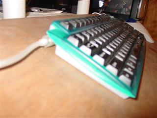
The mouse is then plugged into the other side of the keyboard.
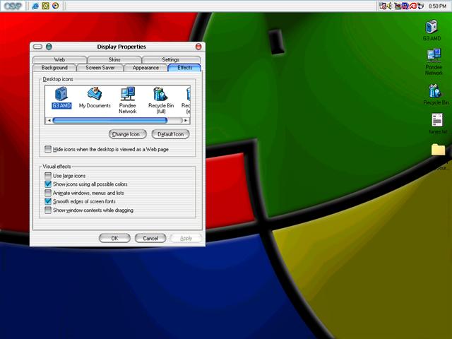
GOODY GOODY GUI
Downloads for the GUI
- The Win/Mac wallpaper seen below
- OSX Icons
- G3 Icons
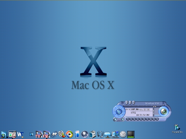
My first bogus desktop. Stardock WindowBlinds gives the wannabe Mac OS look.
One step further was to use a launcher application called Y's Dock.
RANDOM PHOTOS
SOLD IT
The Bad Apple has found a new home - here are the last mods done in my
possession. Really just a request from the new owner
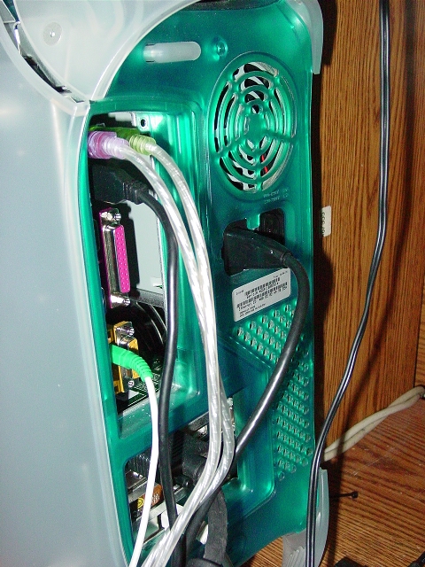
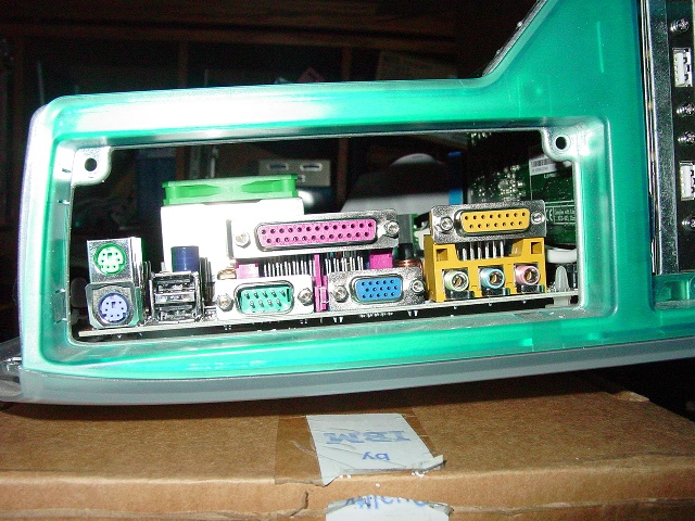
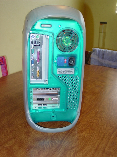
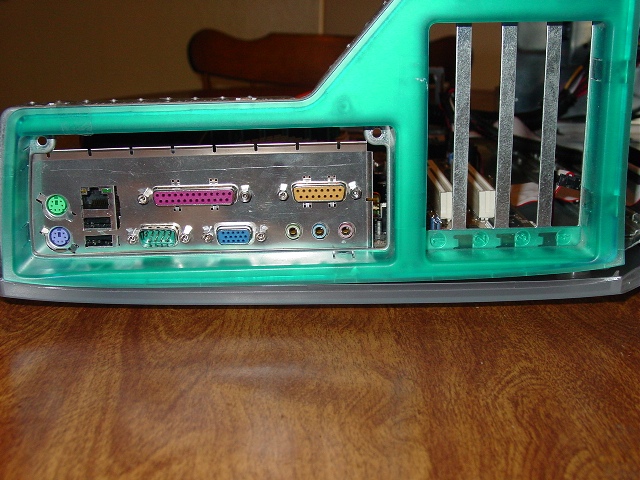
The back panel of the the Asus board with the I/O panel centered, but that
wont allow the AGP slot to be used. I thought about using a low profile
video card such as a Radeon 9200. It has two outputs, one on the card that
would be buried in the case, and another fed by a ribbon cable that I would
mount on the I/O shield or on an expansion slot.
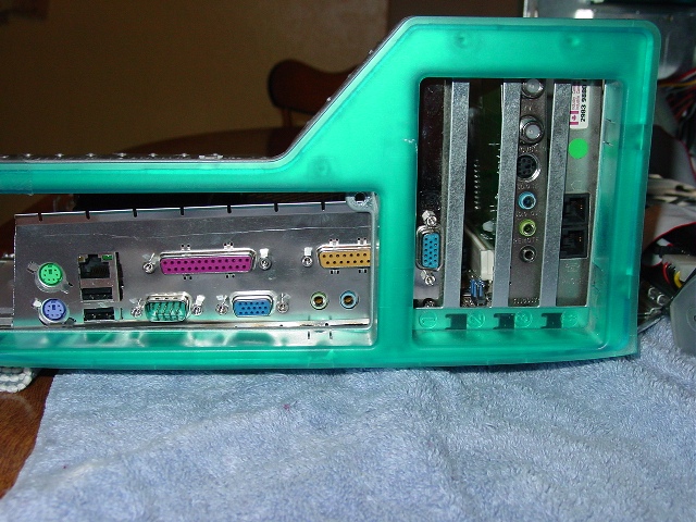
Moving the board about an inch over to allow the use of the AGP slot. The
joystick port will need a shave, and the mic socket is hidden. This is the
same process I first used to make the mounting holes in the case. Fill the
PCI slots, mark the holes with a sharpie, take out the motherboard and drill
two of the holes.
Then place the scrap motherboard tray on the outside of the case and use it
for a template for several more holes.
MORE APPLE TO PC PAGES
iPC - PC in a G4 Case Very clean mod.
Great use of luminescent tape for lighting, and the best illustrations I
have seen for a mod article.
G3 PC -
SystemLogic.net AOpen MX3L motherboard. Very detailed page - pay
attention to the sliding mat under the motherboard and trimming the RAM
sockets.
The “Rotten Apple”
Great paint job. Uses Giga-byte 7VKML motherboard
And in reverse
Blue and White G3 conversion to a PC ATX Case Helps explain the G3's
power switch pin outs.
BAD APPLE MAIL
Hi Bad Apple fans! - Stuff from the mail:
From Alex B
I am happy that I found your web page! I am from Germany and I am also
planning a project like your bad apple project, perhaps you can give me some
answers to my questions. I would be really happy if you would.
Is there enough space between the main board and the cdrom case? or does
or does the main board touch the cage. I have a smaller cdrom lying here
also so I think I can cut the cage about 2 cm
The ASUS A7M266-VM works fine in my application - the only nag with that
board is that the AGP slot does not look readily usable - we'll see. The
short DVD drive is the biggest key to using that motherboard. I recall that
I considered cutting off one of the RAM clips on the unused socket, but
finding the DVD was the key. Can also vouch for the ECS K7SEM, The ASUS
board also requires that the power plug wires be tucked toward the case
front - see the pictures - or they hit the drive cage.
hope you can tell me if the main board is working out good with the case
or do you know any other better board which works.
I have since traded for a slightly better board, an ASUS A7N266-VM. This is
another micro-ATX board with nVidia graphics & chipset, uses DDR RAM and has
a kicking audio setup . It replaced the K7SEM with a few caveats - I needed
to carefully fold the power plug's wires, and the AGP socket is unusable,
for it does not line up with the expansion card slots. The onboard graphics
are ok for now, but I will need to come up with some solution if I want to
upgrade it to a better game machine.
will you sell it?
In a moment. Did in fact trade it for a PIII Laptop.
Footnote 2009. Still one of the most popular pages on barovelli.com. I miss doing all out mods like this. Page reformatted with little or no changes.