Project Mint October 2006

I've acquired a Via EPIA Mini-ITX motherboard to replace the 233MMX on the network. The 233 computer started out as a patchwork of cast off parts - a case that was replaced, a motherboard that was upgraded, an IBM hard drive returned from RMA, that kind of stuff. There comes one day when the junk box suddenly yields enough parts to build a working computer. It has been used as a file swap/software install/webcam server/ and back up. It replaced a mean spirited IBM 9595 that would not do video capture very good, ran at a slow 60 MHz and made too much noise to justify being powered up 24/7.
The Via board is all things on board, sound, video and LAN, is equipped with S-Video and line level TV out, draws less power and is darned quiet.
It's early life in the barovelli den has been simply stuck in the case the 233 came out of. Looks awful tiny in that mid tower. It's been running like a champ, clicking pics from two sources and uploading them, storing files and such. If you look on the Mini-ITX enthusiast site for the motherboard there is a gallery of Mini-ITXs in some very creative configurations. I too want mine in a neat small case, like the pre-fab Shuttle S-24. Cases for this board are scarce, and when you find them they cost about as much as the board itself. That's no fun. So I set off on a mission to can my Via.
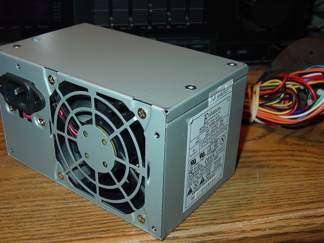
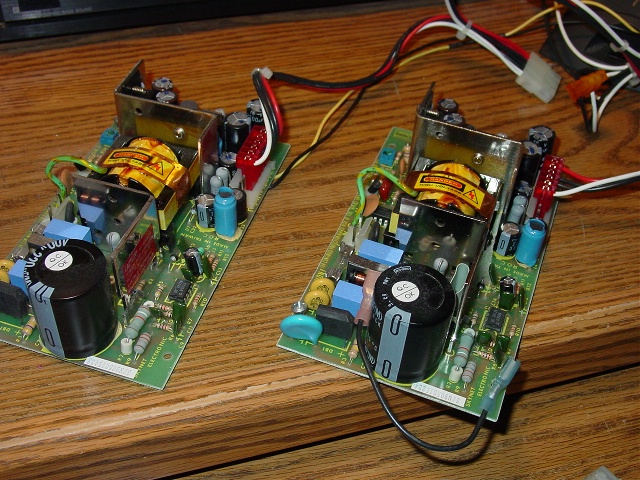
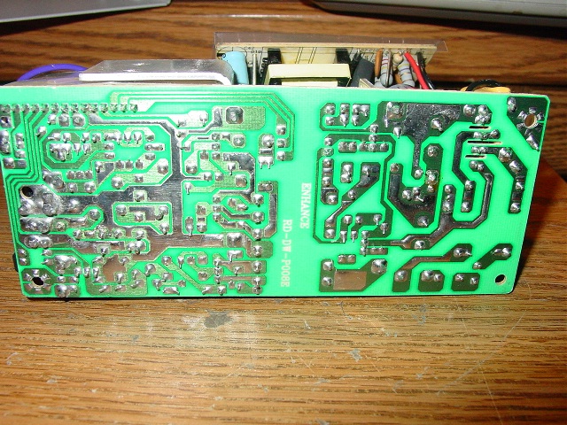
If I am going to put the board in something not originally meant for an ATX form factor board I need an ATX power supply. Don't need a thousand watts for this thing, 100 to 150 should suffice. I went seeking a power supply, and all the regular haunts started at $30 for an e-machine PS. I was browsing the JDR refurb list and spotted this - CASE: MINI ATX & 150W PS $15. I went across the parking lot to JDR and got it. It is a case from a Monorail PC. Looks like it was never used, all the panel connectors were bundled up. I pulled the power supply and set aside the case. Hmmm, now there's something for the NEXT junk box computer.
A $15 Case

The power supply from the $15 case
Still looking for a case. Toying with the idea of putting it in an old eight track player - put the CDROM just right so that the tray would slide out where the tape cart would go, use the 1 2 3 4 program lights for power, hdd, sleep, fan lights, a retro computer. Well the one I located that looks like it will work still has not arrived from the shall we say "less than honest" eBay seller after a month. So Im still looking for other ideas - a toaster oven computer, an AC/DC TV/Computer, a cardboard box computer and some other zany ideas.
I was wandering around in Weird Stuff on lunch break one day and saw some good possibilities. There were some neXT black cubes - but all were operational and high priced. Sun Sparc stations. A UPS. Old Macs, you name it. In the back of the store by the Mac stuff I came to a shelf load of external tape drives. Sayyyyy, that looks interesting.
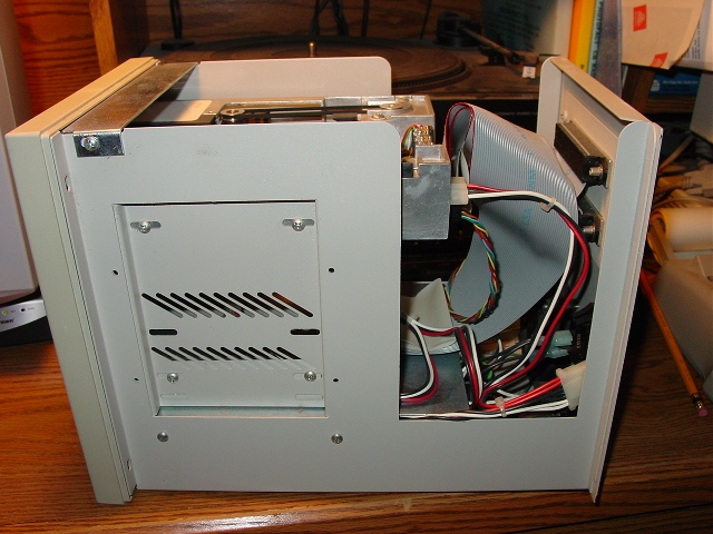
The JMR Electronics Labe

The JMR company looks like it still exists, and is still turning out storage systems. See them at www.jmr.com Now you see where the name Mint came from.
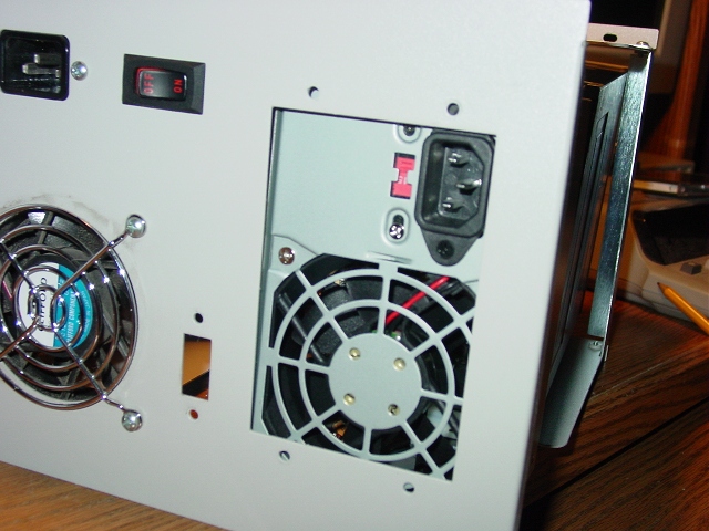
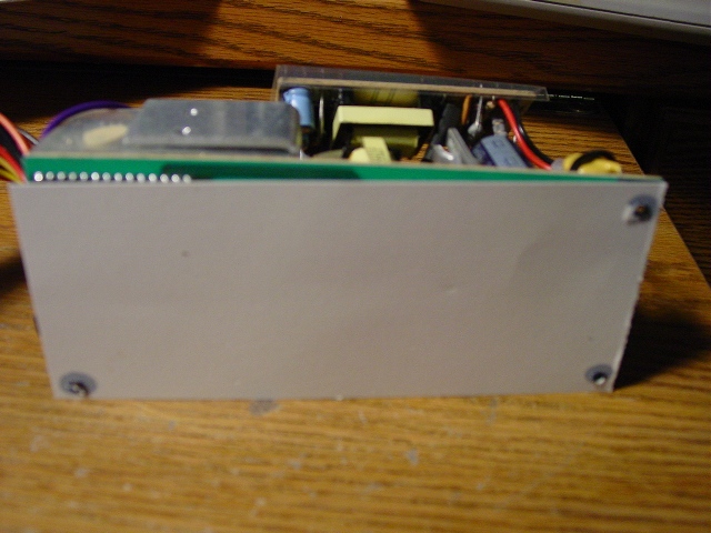
Front

Back

I like the clean look of the front panel, there's no switches, slots or
anything. A half height 5.25"
bay, that full height panel, an LED and a recess for a nameplate. The back
has the power supply,
SCSI connectors and a DIP switch. That front panel though was most
interesting - I envisioned
an LCD panel in that full height bay, so for the meager sum of $10 I took
ownership of a MINT-001
150MB External SCSI Tape Drive. I had no time to lookup any dimensions of
the motherboard or
measure the box. For the price I couldn't complain. Get it to the operating
room, let's look inside:
Side cover off.
Nothing odd. Standard space mounting holes. Most every cubic inch is used
for something.
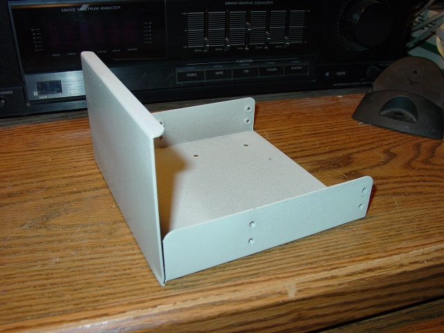
Front Panel Off

I removed the tape drive and the full bay panel. There is a metal shelf
that covers the power
supplies.
Tray & power supplies.

Back with SCSI Panel removed

Bay Filler.
The full height bay is covered with an aluminum tray and panel. The bottom
holes in the tray fit a
3.5" hard drive's mounting holes.
The original purpose of the case - a tape
backup destined for eBay. An Archive 2150S

Back panel disassembles real easy.
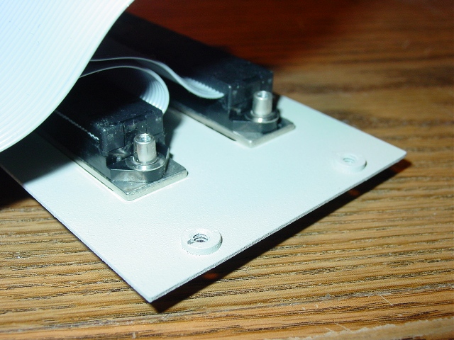
The SCSI Connector panel removes.

The removed SCSI connector panel was assembled with threaded bushings. This
looks like a
very well made piece of equipment.
Got Idle Dust? Close up of the tape drive shows it's collected a bit of
dust.

Twin Power Supplies. In the bottom of the case is two
identical power supplies. One was powering the tape drive, the other was
unused.

The Twin Power Supplies. The power supplies were not redundant.
More Threaded bushings. The SCSI device number was selected
by the DIP switch,
showing it's two threaded bushings. Later on while assembling I figured out
why threaded bushings
are so cool - you don't need to stick your fingers into a crowded case to
hold a nut on the end of
a screw.

A Big Sucking Sound, see? Gutted down to nothing but a fan & power socket.

Looks roomy, eh? Let's
start packing it full of stuff. The CD ROM fits

The Monorail power supply tightly fits

Power supply in the back.
The power supply fits behind the CDROM, but I'd need to customize the IDE
cable & power plug
to get the CDROM hooked up. The power supply does fill the SCSI panel in
this test fit.
Can't have everything fit first time.
The ITX motherboard almost slid right in the case. Almost doesn't count in
horseshoes or case
mods.

Missed it by This Much, Chief
Well, this made me take a long break from the project, trying to figure out how I would need to cut the case to fit the motherboard in it. Should I make a big long slot in the bottom? Should I rethink the whole arrangement? Motherboard mounting goes on hold while I decide what to do and shop for a Dremel tool.
One way to fit

Another way to fit
Fan Replaced

Power supply and hard drive mock up

OK, the new configuration moves the power supply to the bottom of the case.
I took the $15 case's power supply out of its original enclosure to save
space in the box. The goodie box of case mod parts I have been collecting
gets raided for a clear fan with blue LEDs. Another parts test with fan,
power supply, hard drive in an adaptor tray and CDROM. Top is filled, bottom
is filled. Looks like motherboard will go in middle, huh?
Here we go with permanent mounting of the power supply board. Cut out a cardboard template to mark holes in the case for some standoffs.
Underside of power supply
A cardboard template
Use template to drill mounting holes
Power supply installed.

Arrow on fan notes back of unit. 4th hole is in a spot too tightly packed in the power supply, three screws and one of those nylon motherboard spacers will hold it. I used the case's original 3 prong AC socket, and moved the power supply's noise filter to it. I wired in the case's main power switch to switch the AC line. The little circuit board you see hanging off in space had wires just long enough to let me bolt it to one of the fan bolts.
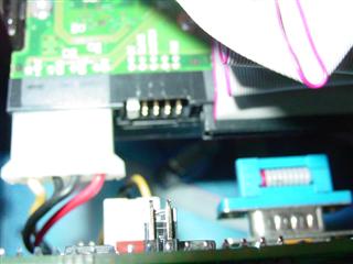
I did not take any pictures of the next fiasco/mess and that's a good thing. I took that shelf that covered the original power supplies and moved it up in a jury rigged fashion. Used a saber saw to cut slots in the sides to clear the motherboard. I drilled 4 holes in the shelf and mounted the motherboard on it. Cut a big hole in the back panel for the motherboard's rear connectors, slapped the ATX I/O shield on and filled the rest of the hole with duct tape. Put a 40g hard drive on the full height filler panel, used the 12/4/2 HP CDRW replaced in an upgrade. (all the drives seen in the mockups are old non-op stuff from the junk box).
Sealed it up and let it run for a few months that way. O/S is Win98 SE. It sat across the room and operated as a file storage unit and web camera uploader. Sort of a burn in while thinking about the final incarnation. Test the stability of the board and the rest of the parts for awhile.
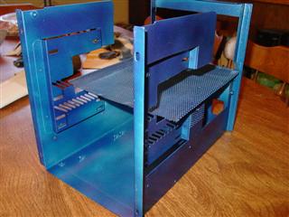
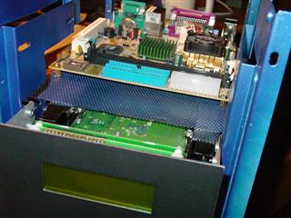
I knew I needed a sturdy base to mount the motherboard on. The old shelf from the case was not wide enough for the motherboard (motherboard is a tad wider than the inside detentions of the case, remember?) I thought about cannibalizing the $15 case for it's motherboard tray and cutting it down to fit. One day at work, I leaned back in my chair and looked up while resting my eyes from the computer screen and saw the ventilation system's grille - eureka! A piece of perforated steel would make a boffo motherboard tray. It would be sturdy, easy to work with and allow freer air circulation than the solid shelf - the burn in test had proved that the fan was noisier with the front panel covered than without a front panel.
The computer was taken apart and fitted into the $15 case. Time to fabricate!
I searched the hardware stores and the electronics junk shops for a piece of steel more suitable than taking the grille out of my office ceiling. Finally found a nice donor piece of steel screen for the tray - it was some kind of cover or shield in an electronic item. It was 'U' shaped with solid end panels so it could cover something like a power supply or set of tubes. The end panels were spot welded and chiseled off easy. Some bending and pounding flattened it out for use.
Motherboard tray.
I folded a piece of paper in the shape that looked like it would work. Using some aluminum bar stock and vise grip pliers I folded the screen so that it would be wide enough for the motherboard and mount down on the inside sides of the case. Three screws per side hold in in.
Side view.

Now, back to mounting a hard drive. Can't use the first method, so I will use a pair of rails to mount a drive to two holes in the side of the case and two in the screen. Best use ever for an 80 mb hard drive?
Dig out the old 80mb hard drive.

Two screws in the tray and two in the
sides.

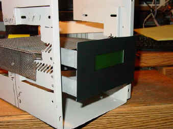
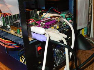
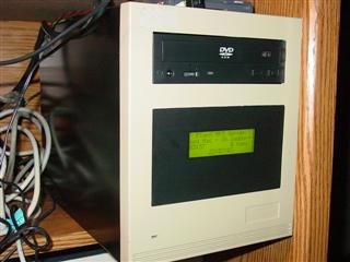
Ooooh! The Matrix Orbital serial display. Now you see the reason for abandoning the original full height tray. A Matrix Orbital 20x4 serial display in a ready made panel. Fits perfect
Final trim of the tray, fire
up the Dremel and trim away excess screen - hey my fingers have to get in
there to replace the power supply.

Next Update - I paint the inside and put the parts back in.
Still needed is a filler/cover for the back panel - maybe a louvered cover.
I also thought about using speaker panel fabric.
Undecided is the power/reset switch for the front, and replacing the single
LED on the front with a pair for power & hdd. Don't want to clutter the
front panel up.
Other upgrades considered are a smart fan for less noise, some strategically
placed LEDs for illumination, portholes to see the illumination and a pair
of internal speakers.
Other accessories for this computer that I have found useful and usable are
Sony USB floppy drive (the Mini-ITX has no floppy interface) .
Blue Interior -
Paint is Rust-o-leum metallic. The inside looks spotty, I know. The sides
are what mattered.
Replace tape with heat shrink. In reassembly all the wires were properly
dressed. No Scotch 88 black tape in this machine. This is one of the jumpers
for the 100VAC to the power supply.

The 110/220 selector was removed and bypassed. Checked with an ohm meter, it was open in the 220 position and closed in the 110 position. I cut it off and joined the wires with solder, again using heat shrink to insulate the splice.
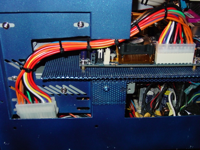
Looking in at the power supply. Power supply mounted with 3/4 screws & nuts.

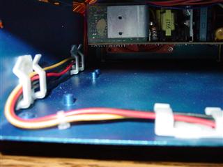
Wire routing. Nylon cable clips intended for
ribbon cables hold this power lead - it powers the hard drive and LCD.
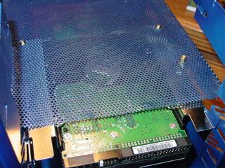
The mesh tray did not have enough metal to tap for the standoffs. They are
held with a nut underneath. The hard drive is held with two screws at the
back and two in the sides, using 5.25" drive adaptor rails. This gives the
tray another two points of support. Think, the RAM socket will be right over
this part, I want some support under it when I insert a stick of RAM.
Garden Variety motherboard standoffs mounted.

HDD Slung under tray.
Matrix Orbital serial display ribbon cable.
Careful measuring and preplanning can assure you that the parts will fit
like they were meant to. Of course there was none of that, really. Pure luck
that the hard drive connectors & LCD connectors all exist without crushing
each other.

Just enough room.
On goes the motherboard.
A little origami with the CDR IDE cable flips pin
one - more of those nylon cable clips keep it snug.

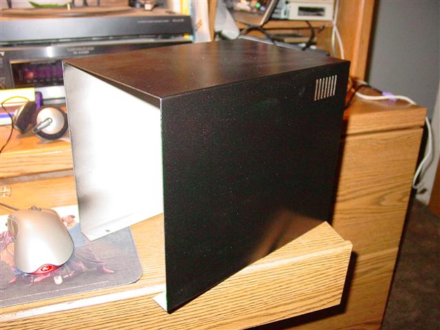
Back In Black. The outer case will be in black - the rear panel got the
black paint to match.

With the cover off in the paint shop (aka basement) I covered the
chassis in cardboard for a heat/sound level test. The Thermatake smart fan
is very different from the blue LED fan - way loud at full speed, but darned
quiet when you turn the trimmer down. But, when you throttle down the fan, a
buzzing noise emits from the fan hub that's just as annoying as the air
rushing noise. I can fiddle with the trimmer to find a sweet spot between
typhoon wind and electric football buzz if I try. Hate it. It's going to get
replaced before final assembly. The "Amazon Air Bubble" covers a drive
bay-sized opening that will hold a panel that will hold the fan speed
control, reset switch and a small audio amplifier to power a pair of
internal speakers.
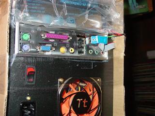
Front of Ghetto Case

The front of the cardboard box computer. The front panel will get painted a
satin black. Some mod sites recommend using auto vinyl dye though I'm
partial to krylon. That crooked CDR is being replaced with a DVD that will
be installed with a bit more attention paid to symmetry.

The system needed no O/S re-install, used the same
components. The LCD display was simple to configure. I used a plug in from
Markus Zehnder to interface with Winamp.

I needed decide on a front panel switch & LED arrangement. All we have now
is two LEDs and a power switch with wires exiting from the back.

The ATX power cable was too short to reach any other way than around the
side. I need to either cut a passageway in the edge or find an extension. In
the meantime the side of the case remains open a crack because of the cable
inside.
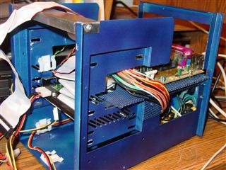
Air Gap. Yah, kool.
As promised the Thermaturkey SmotFan got yanked. Back went the Antec Blue
LED fan. This time I installed a Thermathurkey fan speed control. It's a
three position switch with some resistors to throttle down the fan. The
switch fit perfectly in the original case's SCSI address switch opening. I
got peed at the mix of wires, adaptors, power pass throughs and stuff - I
cut off all the fat plastic plugs and soldered the wires together. Much
neater.
Lights out with the blue fan
Case painting completed
DVD Drive

On the shelf until next update.
Whoa ho! Big update. Via has released an updated version of it's top of the line Mini-ITX board, called the M Series. CPU is upped to 933Mhz, uses DDR RAM, has an updated video system, six channel audio, USB 2.0, Firewire and even a floppy drive. Of course I had to upgrade - mostly for the improved video and audio for this project, which is turning out to be a media PC. I found a new M Board at Frys, it replaced the 800 C3 board nicely. The IDE cable ports are slightly different, but some new origami fixed that. The rest of the connectors were in about the same places
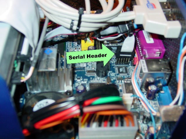
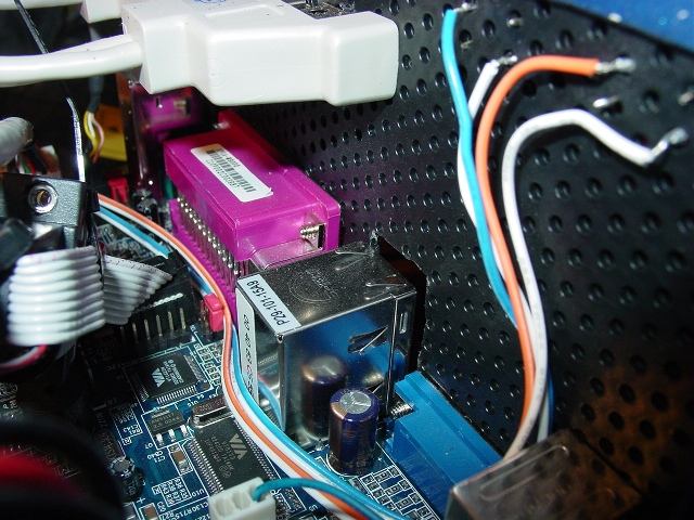
One other bonus is a second serial port. The back panel has one DB9
connector, plus there is a 10 pin header on the board for an additional
port. I was influenced to upgrade on the performance improvements, but the
serial port made the difference between now and later. There was nothing
included to plug into the serial port header, and I thought that it would be
REAL BOFFO if I could use a DB9 and header from an old PCI combo card -
remember those, two IDEs, a floppy, printer, joystick and two serial ports
on an ISA card? - well guess what, VIA did it's homework this time (re:
check the non standard headers on the 800 board for USB). I plugged the
header in, red stripe to pin 1 and plugged in the LCD - worked the first
time.
The 800C3 board was dusted off with canned air, wrapped back up in it's
packaging and put on eBay. Sold the first day for $80. Still a market for
them.
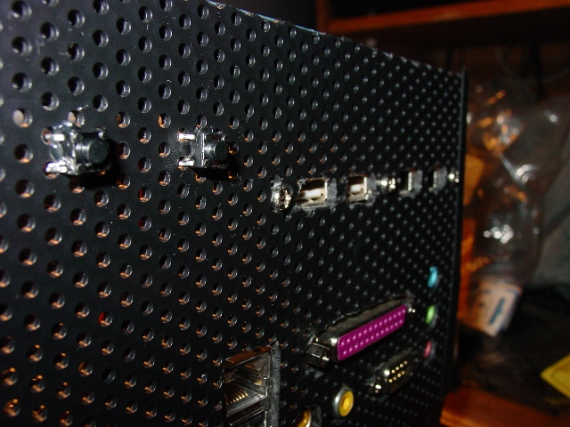
Finishing Up!
Notice the perforated grill back panel - it's from a plastic inbox tray
bought at Staples.
Power & Reset buttons. Still like the clean front panel and do not want
anything messing it up.
Put two momentary switches in the back panel just like an electronic
experimenter's "breadboard".
Power & reset button wires

Power & reset buttons.
Cabling to power & reset buttons. I used some multicolor ribbon cable
for the power & reset buttons. Came off of an old AT case.
No more wires snaking out of the cabinet for these functions.
Power & reset cables end at the header
PS Fan RPM Signal Wire.
Cut a notch in the motherboard tray, filed smooth, filled with hot melt glue
and anchored the power supply fan RPM signal wire so it won't be pinched by
the cover.

ATX Power Extension. Bought an
ATX extension instead
of making a wider notch in the tray.
Case fan throttle switch.

Back panel just before the switches were installed.

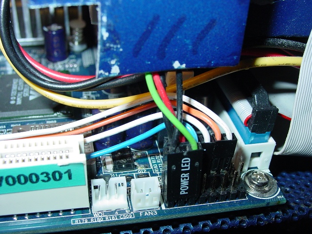
The original power LED on the front
panel was replaced and wired to power LED header. It's green to match the
green LCD Display. The hard disk activity LED is a bright blue LED that
flashes like lightning inside the case when active.
O/S was upgraded to XP Home. Currently system sits on the shelf and plays
MP3s or runs an ICOM
PCR1000 computerized broadband radio-scanner.
Mint Version 2.1
About February 2005, the power supply died. A simple failure to make volts, after running constantly for a couple years. After a few years of mp3 collecting and record sampling, the space available for stuff was starting to dwindle. Here's the upgrades.
Solid State Power Supply
A new power supply would cost either another $15 case or a new unit for $30
or more. After some thought, I bought a PW-200-M 12v solid state power
supply from Mini-Box.com . This is normally used in car computer setups or
in solar/battery operated systems. It runs cool and is dead silent. Since I
have a 12v 20 amp power supply on the desk to power the ham radio, tapping a
lead for the computer was easy. The power supply unit is a 200 watt version.
Since this is a mini-itx with no added video card, it operates just fine.
The vendor's site has a utility to determine the power draw. Told me 75
watts with 2 hard drives, a 5.25" optical and a 2x20 LCD.

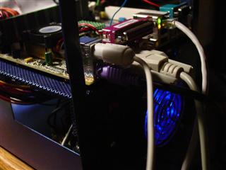
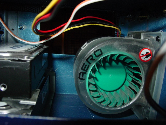
Back Exhaust Blower.
Without that AC power supply in the box, I eliminated the circuit board and
a major source of heat that needed to be vented. I installed a Cooler Master
blower fan in the original fan hole. Another quiet item.
Stacked 120g drives.
To cure the drive space issue, I bought another matching Maxtor 120b 5400
RPM hard disk. I changed the mounting back to a concept originally planned -
a 5.25 tray in the bottom of the case. Some 'plumbers strapping' holds the
2nd drive.

Double Drive
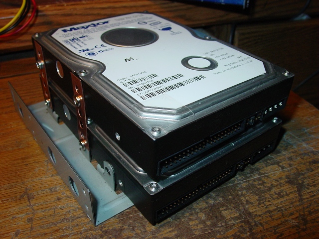
Back in the can
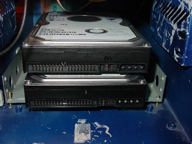
The drives fit perfect. The adaptor tray has 4 threaded holes in the bottom
that allow it to attach with #40 screws. Two drives = more heat, so I cut
out a slot in the lower front of the case and backed it with a grille. I
also moved the power and HDD LEDs behind the grille.

Back of the can.
The back panel was re-fabricated as long as everything else was apart. A
piece of perforated steel was cut out, this time I didn't waste a lot of
time trying to cut all the port holes. Just made the chrome shield fit. I
did mount the itx's additional USB and 1394 (firewire) ports to the back
panel. I fit the stock slot cover over the desired location, drilled a few
holes and then removed the panel to finish up the trim

USB & 1394
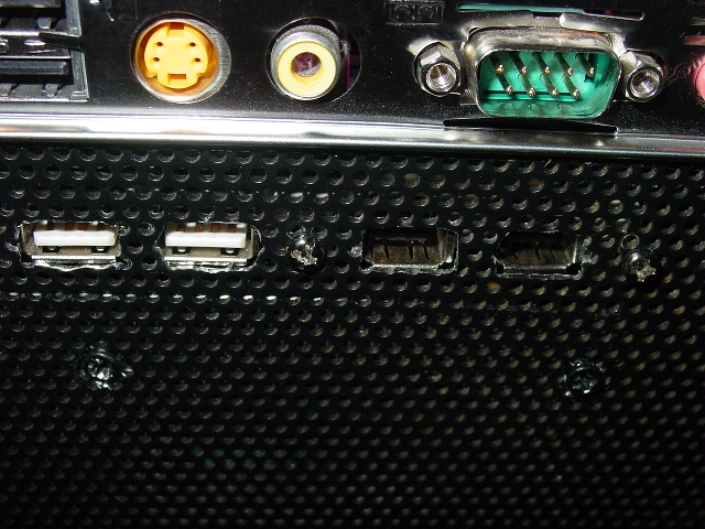
There yah go. 240 gigs, silent & cool. New back panel. Clean, eh? All that is really left to do is fill the power plug hole with a socket suited for the 12v. Until then, the wires just go in the hole. I do like this little machine, it was my first case mod and first nearly all fabricated case. While the power supply (a cheap one at that) did fail, it has never toasted itself and never lost any of the music on it.
OMG! Return of the Mint!
Found another JMR case identical to the original. This one had a Wangtech
tape drive and a Seagate hard disk drive. Picked up at HSC for $15.
Haven't made any plans for it. Networked storage anybody?