Build Your Own DCK-2 For The Kenwood R-5000
30 years late to the R-5000 party and in need of some accessories for the
rig. I use a 12 volt power supply and battery system to run anything that
will run on the desk, the idea is to have less power sucking transformers
making heat and shortening the lives of some fine electronics. There is a
Radio Shack Pro2004 scanner, a Yaesu VX7, the Internet router and a couple
other items all tapped into the 12 volt system, see the web page for the
Power Box Project for it's build &
use.
The Kenwood R-5000 is a fine HF Shortwave receiver that I always wanted but
never could get. I finally got one that needed help for a low price on
Craigslist. It had the dreaded "dots" issue that rendered it useless. Not
having the finer skills to trace and repair a 30 year old radio led me to
send it off to see if it can be repaired. For a price just $20 less than the
radio cost me, it was fixed at
Technical Specialists in Florida. Highly recommend them, worth the cross
country shipping for good work and detailed explanation of what was broke
and the steps taken to remedy it.
Put those two paragraphs together and come up with "how to get the R-5000 to run on 12 volts?". Well, Kenwood did sell an add on kit called the DCK-2 for the radio, it's long out of stock, and if my hunches are correct expensive if one was found on eBay or the like. The Yahoo! Group for the R-5000 is the best source to begin looking for all things R-5000. An article there sent me to Ken's Electronics where I ordered a socket, part # CBJ2B and a red/black power cord with fuse and matching plug, part #CBH2W. Cost with shipping was $11.99
Be aware, this is not a plug & play cord kit. One needs to do a little bit of fabricating to complete the assembly. The power cord is self explanatory. The socket half of this kit ends just south of the socket itself. I still needed to get about five inches of wire from the back panel to the header pins on the power supply circuit board.
Modder's creed says to do as little damage/cutting/desoldering as possible so that you can undo the mod with little left to tell that a modification was ever done. That eliminated soldering the wires to the two pins that were meant for an internal header plug or removing the pins and soldering the wires in their place. To the junkbox for a solution!
I dug through the collection of valuable but unused cords & sockets looking
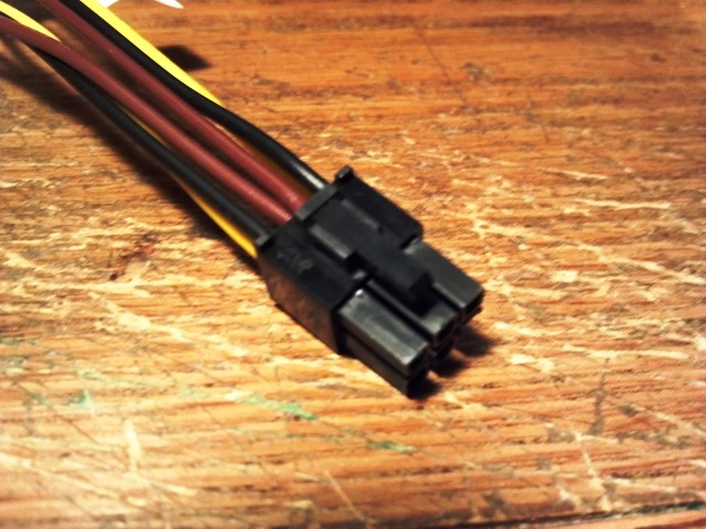
for a suitable socket. What I found is a PCIE power adaptor that came with a
video card. This has two Molex sockets at one end and a PCIE power plug at
the other. Same pin size as a 20 pin ATX power supply cord, two pins
liberated from a dead power supply would also work.
Some careful cutting away with a utility knife freed two usable pins. Trim
enough insulation to solder on to.
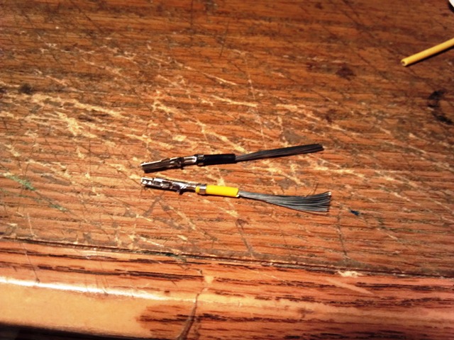
Slide on some heatshrink and solder about 5 inches of wire to the pins
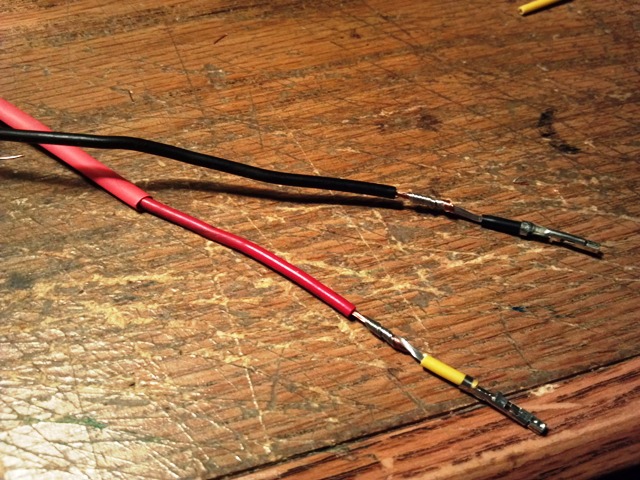
Solder the other ends to the CBJ2B. I insulated that end with heat shrink
too.
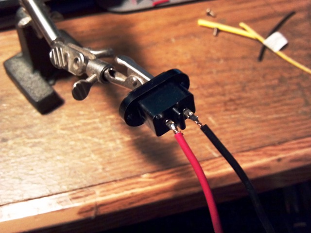
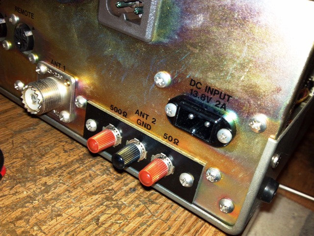
The CBJ2B is an exact fit. Remove the blank that is held on with two screws,
replace with the socket. The same screws go back in. Since the AC socket had
the notch in the bottom I went along with the program.
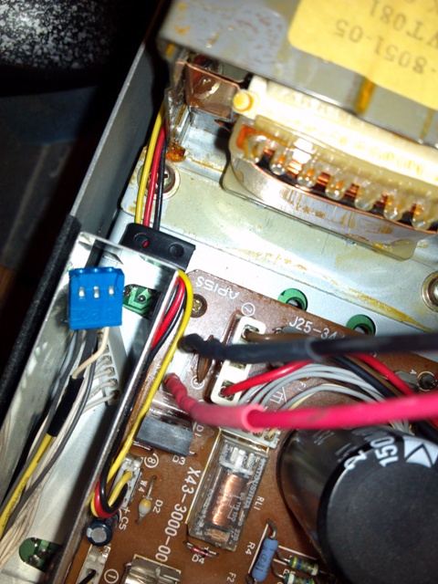
The wires with socket pins attached fit tight on the pins. Camera flash here
blocks the + and - that is marked on the board. Heat shrink goes
all the way to the end. Route the wires around the transformer and fini.
Now that it's on 12 volts it runs cooler, we can close it up and try and
tune in some Radio
Australia
